


July 02, 2014
A variety fo fiber optic connector are used,depending on the cable type and the ethrenet media system.some connector has a key on an inner sleeve along with make the data flow,the ruansmit output of one transceiver must end up at the receive data of the other transceier,When connecting two nearby devices is connected to the receive data at the other device.
For horizontal fiber optic segmengts installed as part of structured cabing system,the connectors on the fiber optic cable should be oriented to achieve the crossover,For example,fiber optic cables are typically terminated in a set of fiber cable LC connectors located at the work area typically terminated in a set of fiber optic cable with two optical fibers in it,fiber#1 is connected to the A conector at the work area end of the segment and the B conector at the work area,and the A connector at the wirting closet.This way ,the user or the network on the horizontal cabling using straight through fiber optic patch cables.

Fiber optic patch cables are used for linking the equipment and components ,we have fiber optic patch cable with different fiber connector types,our low insertion loss and low back reflection .Axen Technologies fiber patch cable is widely applied in Telecommunication Networks ,Gigabit Ethernet and Premise Installations We fiber optic patch cable manufacturer in China,fiberstore supply fiber optic patch cable with different connector and cable type,Fiber optic patch cable is one of most commonly used components in fiber optic network. generally there are two types of fiber optic patch cords: single mode fiber optic patch cords and multimode fiber optic patch cable.
Here the word mode means the transmitting mode of the fiber optic light in the fiber optic cable core. usually single mode fiber optic patch cable are with 9/125 fiber glass and is yellow jacket color, multi mode fiber optic patch cables are with 50/125 or 62.5/125 fiber glass and is orange color.Duplex fiber cables consist of two fiber cores and can be either multimode or singlemode. We also can customize patch cables in any cut length.We offer competitive price for fiber optic patch cable, our company has strictly quality control system and high quality products,the custom fiber patch cable is fast delivery to worldwide customers.
Posted by: mikofy at
06:09 AM
| No Comments
| Add Comment
Post contains 379 words, total size 3 kb.
July 01, 2014
With the rapid expansion of network datacenters for both the private and public sectors, Amphenol Cables on Demand is seeing explosive growth in high-speed copper and optical cable products capable of speeds in excess of 10-Gigabits per second..As networks rapidly migrate to higher bandwidth over increased distances, the need for quick, easy-to-deploy solutions and future-proof designs from a trusted source is essential. Fiberstore,to deliver solutions that are designed to be better and create increased flexibility, greater efficiency and a superior network design.
fiberstore offering a complete line of products and systems ranging from high density fiber modules,cassettes and adapters to patch cords and harnesses, as well as fiber enclosures and trunk cables. This complete solution set provides the exceptionally high performance level that the Ortronics product line is known for, and unsurpassed integration with the rest of the physical infrastructure offering, such as some of our most popular cable items include our Fiber Optic Patch Cord,lc fiber cable,sc fiber cable and so on.

Fiber optic cabling is the medium of choice for longer distance and challenging cabling runs. These cables are thinner than copper patch cords and immune to EMI (Electromagnetic Interference) making them perfect for riser runs and uplink cables. There are two basic types of fiber cabling, single-mode and multi-mode.Howerver,there are something should be pay attentios when you are using the fiber path cords,Wavelength transceiver modules must be identical at both ends of the fiber jumpers, that must be the same at both ends of the fiber wavelength optical module, a simple distinction is the color of the light module to be consistent. Under normal circumstances, shortwave optical module using multimode fiber (orange fiber), long wavelength single-mode fiber module (yellow fibers) to ensure the accuracy of data transmission. Do not use excessive fiber bending and circling, this will increase the light attenuation in the transmission process. After using fiber jumpers must use protective sleeve protected fiber optic connector, dust and oil will damage the fiber coupling.
Fiberstore manufactures Optical Splitters and many kinds of fiber optic patch cords.Then Provide very fast logistics, as well as a very unique service system.If you want to customize products such as fiber optic cords, fiberstore is definitely a very good choice.
Posted by: mikofy at
08:59 AM
| No Comments
| Add Comment
Post contains 373 words, total size 3 kb.
June 30, 2014
While early optical connector and cabling solutions themselves provide advantages over copper,more recent optical solutions extend this advantage considerably.In the mid-1980s,optical fiber was introduced into data prossing communications.At regularintervals,suppliers debeloped higher density connectors in lockstep with optical transceiver manufacturesand original equipment manufacturers (OEMs).Multifer connectors have been developing for some time.Early ESCON connectors were quite bulky for handling two fibers.Denser solutions such as the MPO connector allowed the same two fibers to be contained in less linear space.Liner board space.Linear board space,though,is not the appropriate measurement of density.To make the most efficient use of the available space ,designers can resort to multirow fiber arrays in which one has to think in two dimensions (width and height).As a result,the same MPO connector has been expanded to contain 72 fibers in the same liner space as was occupied by only two fibers.Recent Electrotechnical Industry Association/Telecommunications Industry Association(EIN/TIA) standards proposals call for arrays of up to 96 optical fibers contained in this same size connector,and technical proposals postulate over 250 fibers in the same linear space.
The resulting improtant metric is the toal mating density(TMD)for a given total mating area (TMA)。A two-dimensional(2-D) connector can greatly increase TMD.A two-fiber MPO connector would,for example ,have a TMA of 3.0x 5.0mm=15mm^2 and thus a TMD of 2 fibers/15mm^2 and thus a TMD of 2fibers/15mm^2=13 fibers/mm^2.Conbersely,a 72-fiber MPO style connector has 6 rows of12 fibers for a TMD of~4.8 fibers/mm^2.While the transition from an ESCON connector an MPO connector increased fiber density by only a factor of about 2.5,the transition from two fiber MPO connector to 2-D MPO conectors has increased fiber of 90 times over the past 20 years, driven largely bu the move to 2-Darrys.
MTP MPO Fiber Cable is offered for various applications for all networking and device needs like 100 Gig modules. It uses a high-density multi-fiber connector system built around precision molded MT ferrule. Fiberstore’s mpo fiber cable are available in UPC and APC finishes, support both multimode and single mode applications, and optional lengths available. Our MPO/MTP fiber cable is with push connector IEC 61754-7 and TIA/EIA 604-5A compliant and offer low cost per termination for high density applications. The MPO/MTP fiber cables are tested with guaranteed quality, and they can be installed easily, which saves time and money.
By themselves thees dense connector solutions can greatly simplify structured cabling solutions by aggrgating fibers in systems employing traditional serial or small parallel fiber optic transceibers in systems employing traditional serial or small parallel fiber-optic tranceivers. The increased cabling density can directly reduce the space demands of systems.With properly designed optical can provide very reliable and consistent assembly process,high-density optical assemblies can provide very reliable and repeatable performancd,meeting the needs of the server and storage community.Compared with copper interconnections,these is a dramatic size and weight savings and a cost benefit,Considering these factors alone,one can build a strong case in favro denser optical conneections.Howerver,interfacing these dense connectors directly with corresponding dense energy -efficient active optical can result in the major benefit of increasing board channel density while simultaneously lowering the cooling requiremnts.

Cost-effective multimode polymer waveguides, suitable for use in high-speed on-board optical interconnections, are presented. The fundamental light transmission properties of the fabricated waveguides are studied under different launch conditions and in the presence of input misalignments. Low loss (~0.04 dB/cm at 850 nm) and low crosstalk (<-30 dB) performance, relaxed alignment tolerances (plusmn20 mum) and high-speed operation at a 10-Gb/s data rate are achieved. No degradation in the high-speed link performance is observed when offset input launches are employed. Moreover, a range of useful waveguide components that add functionality and enable complex on-board topologies are presented. The optical transmission characteristics of the fabricated components are investigated and it is shown that excellent performance is achieved. Excess losses as low as 0.01 dB per waveguide crossing, the lowest reported value for such components, and bending losses below 1 dB for 90-degree and S-shaped bends are obtained even with multi mode fiber optic cable . Moreover, high-uniformity power splitting and low-loss signal combining are achieved with Y-shaped splitter/combiners while a variable splitting ratio between 30%-75% is demonstrated with the use of multimode couplers. Overall, the devices presented are attractive potential candidates for use in on-board optical links.

Optical interconnect is a way of communication by optical cables. Compared to traditional cables, optical fibers are capable of a much higher bandwidth, from 10 Gbit/s up to 100 Gbit/s.The technology is currently being introduced as a way to link computers to mobile devices, as well as on motherboards and devices within computers.
Posted by: mikofy at
07:01 AM
| No Comments
| Add Comment
Post contains 762 words, total size 6 kb.
June 27, 2014
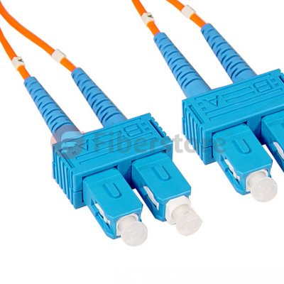 SC-SC Plenum Duplex 62.5/125 sc multimode, with SC to SC termination, this fiber optic patch cable is specificially designed for ethernet, multimedia, or communication applications. The SC connector features a push-pull locking system. The plenum rating provides the fire protection required to run this cable within walls and air plenums without using conduit. The patented injection molding process provides each connection greater durability in resisting pulls, strains and impacts from cabling installs.
 lc lc multimode has a bayonet-style housing and a long spring-loaded ferrule hold the fiber. They are available in both multimode or singlemode versions. Horizontally mounted simplex and duplex adapters are available with metal or plastic housing.
Posted by: mikofy at
04:15 AM
| No Comments
| Add Comment
Post contains 454 words, total size 4 kb.
June 24, 2014
There are some related duplex sc-sc patch cord from our store, the following picture, you can see.
This is an "Yellow" single-mode cable with a 9 μm core and 125 μm cladding diameter. The cable has a color-coded Dual SC connector on each end. Cost-effective solution that provides high bandwidth and transmission rates over longer distances. With SC to SC termination, this high-quality fiber optic patch cable is specifically designed for Gigabit Ethernet applications. The patented injection molding process provides each connection greater durability in resisting pulls, strains and impacts from cabling installs.
The first step in verifying the polarity of the chanels shown in Figure17.28 is to de-enrgize the equipment at both ends of the network,Since lathced duplex patch cords are used,unlug both connectors from both ends of the patch cords at each of the network.Using the continuity tester,verify that connectors on each end of a patch cord are oriented so position A goes to positionB .You can do so byinserting the ferrule of the A position connector into the continuity teseter as shown in Figure17.31.
With the connecetor inserted,energize the continutity tester and check to see if light is exiting the optical fiber in position B at the oppotite the path cord.if light is exiting the optical fiber in position B,the polarity is correct.if ligtht is exting the optical fiber in position A,the polarty is not correct.With the continuity tester still attached and energized ,unlatch both conectors,seap locations,and relatch.Verify light is extiing forem the optical fiber in positon B.Repeat this for the other fiber optic patch cords and correct as necessray.
With both patch cords properly configred,the next step is to verify the polarity the horizontal cabling .To minimize accses to other horizontal cabling,you should work from the equipment outlet to the pach panel.REmove the cover of the equipment outlet and plug both connectors at one end of the path cord into the receptacles on the equipment ontlet.Do not disturb the horionta cabling connections.
Insert the ferrule of the A postion connector at the end of the patch cord into the continuity tester as shown earlier in Figure17.31.With the connector inserted,engrgize the continuity tester as shown earlier in Figure 17.31.With the conector inserted,energize the continuity teser and check to see if light is exiting the horizontal cabling optical fiber in positionB at the pach panel.If light is exiting the optical fiber in postion B,the polarity is not correct.With the continuity tester still attached and energized,unlatch,Light should be exiting from the optical fiber in positionB.Reinstall the equipment outtlet cover.
Posted by: mikofy at
07:54 AM
| No Comments
| Add Comment
Post contains 520 words, total size 4 kb.
June 21, 2014
In addtion to diamond rings, there are a lot of other options out there to consider, such as handmade silver rings. They're fashion, lovely, and they don't all come with the baggage of a diamond—especially, they're not as expensive. More and more people choose to buy the rings online now.
Engagement rings and wedding rings sold at store are 20 percent more expensive than that from online. That's because you're not paying the extra overhead costs of traditional retailers. The online jewelry and watch industry has grown to $9.8 billion, increasing an average of 2.9 percent a year for the past five years, according to IBISWorld, an industry research firm. And online retailers, for example, Chrome Hearts, usually have more styles to choose from than their physical rivals.
Chrome Hearts rings Feature
1.Expert Design
Their experts have close contact with the rock singers to create rings featuring designs important to their punk style. Chrome Hearts has customized rings using the highest-quality materials.
2.Precision Details
Their cutting-edge toolmaking and technology to certify the intricate and precise. To get exactly the look, they first make a wax pattern of the ring and adjust it to make sure it is a perfect fit!
3.Enhanced Details
Their jewelry craftsmen then clean, smooth edges and shape the ring to make sure the special details are perfect and clearly stand out.
4.Perfectly Polished
To make ring truly shine, Chrome Hearts have a special highlighting step that pulls out more of the individual details.
5.Impeccable Inspection
Upon passing the scrupulous inspection of Chrome Hearts's Quality Control team, your ring is ready to be shown off! Jus take as much pride in your ring as you do.


chrome heart ring sale here.
Posted by: mikofy at
09:23 AM
| No Comments
| Add Comment
Post contains 289 words, total size 3 kb.
June 16, 2014
1. working principle of the module
Long-range fiber optic sfp module products for unity with APD receiver module, work rate 2500Mbps, transmission distance 80km, electrical interface can hot swap without power, dual LC optical interface plug type, with DDM digital diagnostic functions. Transmitter and receiver module is divided into two parts. LC driven in part by an integrated emission control circuit with APC and DFB-LD components. The integrated circuit receiving LVPECL logic level signal and provide for the LD bias and modulation currents, APC loop current size according to the size of the generated light emitted optical power LD, to achieve automatic control of emitted light power work can be. The integrated circuit with a transmitter shutdown; receiving section includes APD TIA components and limiting amplifier chip. CML limiter amplifier output logic level signal and a signal having a LOS alarm function.

2.5 G electric modulation signal, through TD difference data input feet enter into the light module launch part, through the module within the Laser Driver produces light modulation signal data, through the optical fiber transmission.Optical signal to receive data, through the optical module will receive part of the light signal into electrical signal modulation and shaping amplifier, in through the module of Rx difference data feet output.So as to realize the long-distance transmission of data through the optical fiber.
2. based on SFP-MSA Multi-Source Agreement design
SFP-MSA Multi-Source Agreement sets out our main design SFI 'need to meet the mechanical dimensions, package, module definition and application circuit Goldfinger peripheral module inserted row, making it compatible with a wide range in the optical communication equipment. According to the requirements of the agreement, we have designed single mode fibre sfp housing meets the requirements of the agreement.
3. Based on the design of SFF-8472 standard
SFF-8472 standard defines the main multi mode sfp digital diagnostic functions and modules to achieve the principles of internal software storage spaceStandard definition, making the system vendors through MOD-DEF modules (0) ~ MOD-DEF (2) of the three legs of the operating parameters of the software control module for real-time monitoring.
According to the definition of this standard, thismulti mode sfp designed to its operating voltage (reported accuracy of ± 3%), operating temperature (reported accuracy of ± 3 ℃), transmitted optical power (reported accuracy of ± 3dB), transmit bias (reported accuracy of ± 10 %), received optical power (reported accuracy of +3 dB) for real-time reporting, enabling the SFP digital diagnostic functions.
4. light-emitting device selection
Because the module work rate reached 2.5G, transmission reach 80km and small packages. So we use the LC 1550nm DFB laser with coaxial isolators as emitting device according to the design. (1) DFB device characteristics: DFB lasers belongs to a single longitudinal mode (SLM, Single LongitudinaL Mode) semiconductor lasers. Compared SLM semiconductor lasers with Fabry-Perot laser, it is no longer independent of the resonant cavity loss pattern, but different vertical mold design paired with different losses.
Posted by: mikofy at
03:10 AM
| No Comments
| Add Comment
Post contains 495 words, total size 4 kb.
June 13, 2014
Read by the microcontroller optical modules and CDR-related memory, and in accordance with the parameters that need to be read LCD display real-time, so that the results intuitive and easy to understand. While connected via serial port and external facilitate debugging. In this system, SFP module implemented by CDR I2c bus communication with the microcontroller. fiber optic transceiver module via an external device access signal, the photovoltaic modules into an electrical signal, and then after the clock data recovery CDR, bit error rate, measuring extinction ratio, sensitivity and other parameters with normal test results to see whether the correct comparison. While the optical module is connected via the optical interface with external microcontroller to communicate with the outside world through the serial port for data exchange, each signal via SMA connector leads, as required by coaxial cable to connect the debugger, it is easy to debug.
2.2 optical module monitoring platform software design
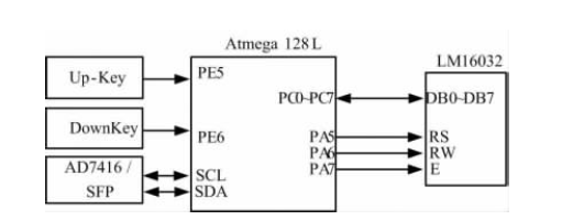
2.2.1 software system design structure with a brief description of the microcontroller Atmega128L LCD (Model LM16032) using parallel data transfer, three control bit MCU PA5 ~ 7 and LCD (RS, RW, E) is connected, plus two control LCD display on the Up-key and turn the key down key DownKey and SCM PE5 and PE6 connected to the microcontroller interrupt the way to achieve the appropriate control. SFP microcontroller reads the data from the relevant parameters I2c bus after transmission through parallel to the LCD display. Using the timer mode, so With a frequency greater than 24MHz refresh LCD display.
3 main parameters read
3.1 Temperature parameters read
Because of the module can be used in a high rate of system and has the appearance of small, the layout of the they are usually very compact.In these applications sfp transceiver of rectangular box shape affect the cooling air flow, thus partially weaken the advantages of easy to use, so the temperature inside the module as a useful parameter to measure the long-term stability of the device and device of electro-optic specifications conform to the degree of life.3.2 read voltage parameterIn the SFP working voltage can through sensor installed on the internal PCB circuit for measuring.These measurements can also be used to observe the working voltage drift.And according to the experience can be linked with a given SFP pin or monitoring failure due to the system power supply environment caused by the large voltage fluctuation.
3.3 Read bias current
When reliability prediction has been the most effective transceiver module parameter is the laser bias current, typically used in integrated optical transceiver modules are in constant optical output power mode. Through a closed loop feedback circuit to change the laser bias current so as to stabilize the laser output power. Since the laser efficiency and the threshold values ​​are changed with temperature, and many modules are required to change the laser bias current so as to stabilize the optical output power of the laser, the laser bias current if the variation is not as temperature or voltage changes caused, it shows that the laser potential stability problems.
4 Based on the test platform module parameters
4.1 Bit Error Rate Test
For error test mainly through error instrument, optical module, and the CDR from ring, through error instrument observation error rate is less than 1 hour 10-12.Test procedures and results![]() 1) good connection test equipment.(2) the work continuously for an hour, once every five minutes record error rate.(3) the bit error rate has been less than 10-12.
1) good connection test equipment.(2) the work continuously for an hour, once every five minutes record error rate.(3) the bit error rate has been less than 10-12.
Posted by: mikofy at
03:17 AM
| No Comments
| Add Comment
Post contains 586 words, total size 4 kb.
June 11, 2014
In recent years, fiber optic communications network has achieved rapid development. Optical transceiver module as one of the key technologies of optical fiber communication network is widely used in a variety of optical communication systems. Smart SFP optical module, which uses digital diagnostic functions fiber optic sfp module, it can achieve real-time monitoring of network management unit transceiver module temperature, supply voltage, laser bias current, and optical power transmission and reception. The measurement of these parameters can help identify the location management unit fiber link failure occurs, simplify maintenance, improve system reliability. Optical modules to achieve real-time monitoring capabilities for effective life prediction module, isolation system failures, as well as to verify the correctness of the module status during the installation and commissioning of high practical value. The author based digital diagnostics, design and implement a monitoring platform of an optical module. The platform uses the microcontroller via a 2-wire serial bus to access the modules to read and deal with related parameters, while module parameters to be read in real time through the LCD display. And with CDR (clock data recovery) section, can signal clock recovery and data retiming, as a basis for hardware monitoring module in the relevant technical specifications designed monitoring platform.
1.1 the basic principle of digital diagnosis
In the SFF-8472MSA, the specification of the digital diagnostic functions and related SFF-8472 for details. The specification, in the northern part of the circuit board module detection and digital signal parameters. Then, provide calibrated results or provide digitized measurements and calibration parameters. This information is stored in standard memory results in order to read through the two-wire serial interface. Retained the originalbidi sfp transceiver / GBIC Address Address A0h at the map and added a 256-byte storage unit at the address A2h SFF-8472 in the agreement. This information is stored in addition to providing parameters to detect, but also defines the alarm flag or alarm conditions, the state of the mirror each pin, limited number of control and user-writable storage unit.
1.2 The role of digital diagnostics
(1)intelligent life prediction 10g sfp module provides a prediction methods of the parameters of the laser degradation of real-time monitoring.Light module within the light power feedback control unit will power output control at a stable level, power control is by increasing the laser Tx_Bias (offset current).Therefore, we can through the monitoring of the laser bias current can be used to predict the life of the laser.
(2) fault location In optical links, the location of the fault occurs is critical to business fast load positioning.Fault location, need comprehensive analysis of status, a pin and measuring parameters.Through to the detected Tx_power (sending power), Rx_power (received power), Temp (temperature), Vcc (voltage), Tx_Bias (offset current) warning and alarm status, Tx Fault image of the state variables (alarm) and RxLOS (receiving signal loss), and other information for comprehensive analysis, can locate the Fault is in the module or on the lines, in local module or in the remote module.
(3) compatibility verification by monitoring the voltage is outside the specified range, whether the received optical power overload or below the receiver sensitivity, temperature exceeds the operating temperature range, etc., work environment analysis module meets the data sheet or compatible with the relevant standard.
Posted by: mikofy at
03:18 AM
| No Comments
| Add Comment
Post contains 548 words, total size 4 kb.
June 09, 2014
The thing is that sunglasses appears on our face and it's our visit card, as we showcase our overall style and look, that's why it's very important to show people our knowledge about fashion and trends that we follow. For the ones pursuing fashion, sunglasses is the same as bags, hats, shoes and clothes , are being changed every season every year. These days sunglasses and Chrome Hearts optical glasses frames are coming in various colors and shades. New 2014 season offers different styles, sizes and shapes. What sunglasses are look like in 2014? Look here — photos of the most stylish newChrome Hearts Sunglasses 2014.


Posted by: mikofy at
02:00 PM
| No Comments
| Add Comment
Post contains 109 words, total size 2 kb.
Introduction
In the optical communication products, optical module occupies has a very important position. Optical transceiver module as one of the key technologies of optical fiber communication network, is widely used in synchronous optical network SONET) and Synchronous Digital Hierarchy SDH), Asynchronous Transfer Mode (ATM), Fiber Distributed Data Interface (FDDI), as well as Fast Ethernet and thousands Gigabit Ethernet and other systems.
In the present optical communication products, fiber optic transceiver module has been more popular than others, SFP GBIC module module volume ratio reduced by half, but also supports hot-swap capabilities, has been widely used. Meanwhile, in the various existing networks needed optical transceiver module types, more and more requirements are also increasing. To meet the ever increasing performance requirements of the system,Optical module continues to develop intelligent, fast and high-density interconnect direction.
Intelligent SFP optical modules, namely USES the fiber optic sfp module of digital diagnosis function, will become a new generation of optical transceiver module integrated in the window.It can realize network management unit real-time monitoring the temperature of the transceiver module, power supply voltage, bias current, as well as the transmitting and receiving optical power.Through monitoring of these parameters, we can help system administrators predict the life of the light module, fault isolation system and authentication module in the installation of compatibility, etc.
A smart SFP optical module system design
1.1
Transmitting section
The main role of the light-emitting process in the optical transmission module is to convert the optical signal into an electrical pulse signal is a pulse, the electrical signal is input, the output optical signal. Transmitter module, mainly by the laser driving circuit and the TOSA. Which TOSA backlit by the laser diode LD and PD components. LD is used in vertical cavity surface emitting laser VCSEL.
First electrical modulation of the laser drive lasers to meet the input digital fiber optic communications system required drive signal, the drive signal from the bias current IbiasAnd the modulation current Imod composition, the laser emits an optical signal corresponding to the driving of the driving signal, the optical signal is coupled into the optical fiber and transmitted to the receiving end. In this scenario, the laser driver selection MAX3286.
Laser driver with the functions of automatic power control (APC), APC circuit using the backlight diode in the TOSA, monitoring laser the size of the backlight.When the optical power is less than one rating, through increase the drive current feedback circuit, laser output power increases as the rated power value.Conversely, if the optical power is greater than a certain rating, is through feedback circuit reduce drive current, laser power output is less.APC circuit can dynamically adjust the laser power, therefore, the size of the bias current, can automatically compensate laser due to the change of ambient temperature or aging caused by the change of the output optical power, keep the output optical power range is relatively stable.
1.2
Receiving part
The main role of the receiver module is attenuated after
deformation weak optical fiber cable transmission signal to a pulse electric pulse signal by photoelectric conversion, and give sufficient amplification, a standard reduction of the digital pulse signal. Optical receiver module schematic shown mainly by the photodiode PD, a preamplifier, a limiting amplifier and other components. Which photodiode and preamp integrated package together constitute ROSA.
A photodiode is a core device of a digital optical receiver, an optical pulse signal will be the electrical pulse signal by photoelectric conversion, commonly used are PIN photodiodes and avalanche photodiode APD. Optical signal from the optical interface enters the photodiode PD, is converted into a weak current, the current through the pre-amplifier and converted into a voltage level is amplified to an appropriate level.
Effect limiting amplifier output of the preamplifier is the magnitude of different amplitude analog signal into a digital signal, these signals can be amplified. To photoelectric detectors with a good match and get the low-noise and wide-band preamplifier gain is not too high, the preamplifier output voltage amplitude is usually from a few millivolts to tens of millivolts, such small signals can not be directly output optical module is therefore necessary to further enlarge the signal; the other hand, the photodetector detects the light signal from the amplitude of the current signal in a defined tolerance level, the tolerance limits of the capacity of the fiber considered Poor, splice loss and the parameter fluctuations caused by temperature and aging, however, the data for further processing, the signal amplitude is preferably a constant value.
Therefore, limiting amplifier requires a certain dynamic range, which usually requires a dynamic range of more than 20dB.
1.3
Digital Diagnostics DDM part
Digital diagnostics mainly composed of MCU to complete. By temperature MCU, the network management unit may receive real-time monitoring module, the power supply voltage, laser bias current and the light emitting and receiving power. By measuring these parameters, the management unit can quickly identify the specific location of fiber link failure occurs, simplify maintenance, improve system reliability.
Five DDM parameter acquisition circuit for acquisition by the first conversion, the inputs to the ADC, ADC five circuit analog voltage into a digital signal sent by the decoder circuit is stored in a memory support DDM corresponding address bit . Transmission of information via a two-wire serial interface (SCL clock line and data line SDA) to achieve.
Posted by: mikofy at
02:51 AM
| No Comments
| Add Comment
Post contains 894 words, total size 6 kb.
June 06, 2014
High-speed digital circuit design means that if the rise time of the signal propagation delay times of less than 4, PCB.The signal on the board can present transmission line effect, such a design is called high speed digital circuit design.And the Series digital circuit design method is different, high speed digital design need SI simulation analysis.SI simulation analysis generally divided into before wiring two process simulation and post layout simulation, its main task is found in the system design process and improving the sI problems, ensure the quality of signal transmission functions and the right time, is to ensure that the key step in the design is successful.
Gigabit SFP optical signal transceiver card is mainly composed of four modules: (SFP) fiber optic transceiver module, the large capacity data cache (SDRAM) (PCI9656), PCI bus interface module, control module (FPGA).Implementation of main function is to be able to send and receive gigabit Ethernet optical signals, on the physical layer and data link layer handling gigabit Ethernet protocol, IP packets and through PCI bus is extracted in the computer's memory.Demand support vet2 PCI card. Agreement support DMA transfer mode, data transfer rate is not less than 125 MB/s.
Light module in the design of input and output electric signal frequency up to 1.25 Gbps, using the LVPECL difference signal, the gigabit difference signal simulation discussed in literature [3].First of all, establish simulation model as shown in figure 7.Single line impedance 50 1000 f2 differential impedance (X1), signal rate of 1.25 GHz.Outl LVPECL difference output IBIS model for sfp transceiver module, Inl for FPGA LVPECL differential input IBIS model.
Design by using based on SI simulation analysis and design of high-speed signal PCB wiring rules, solved the gigabit sfp ports signals in the process of sending and receiving card design, signal integrity problems of cloth plate a successful, completely meet the requirement of design index, and avoid the repeat design from the signal integrity issues.In the process of high speed digital circuit design, based on SI simulation analysis early in the design of the product as much as possible to solve the signal integrity problems, so as to minimize the product cost, shorten the development cycle.
Posted by: mikofy at
02:35 AM
| No Comments
| Add Comment
Post contains 373 words, total size 3 kb.
May 30, 2014
Of course, we will be told that this year will be the year 10Gb / s Ethernet great development over the past few years as we have been repeatedly told that. The reason is not because of technical ability -? 10 gigabit ethernet sfp has stabilized for some time - but because of the cost.
When 1000 base-t technology dominate the market, you can take 10/100 of your device is inserted into the 10/100/1000 switch, and then it can work.More important, 1 gb/SEC Ethernet port on a switch cost has dropped to very low, so that if we don't need to maintain high throughput on these links, we all feel that they spend money on port.If we need 1 gb/SEC Ethernet is there, even if we don't need most of the time.
Some people believe that 10 gb/SEC Ethernet will follow the same pattern, but even the optimists are also beginning to forecast by 10 gbase - 2014 T to be made more than the alternative solution deployment.Even if by that time, we are still going to deal with the various types of 10 gbe interface type.The price is still an obstacle.The price of each switch port 1000 base-t can only $10, but the most common type of 10GBASE SFP+ - the switch port cost is 300 dollars, I expect this costs can drop to below $200 by the end of the year.10 gbase - T still more expensive than the unit switch port costs of SFP +, and compared with the SFP +, 10 gbase - T more rare on the market.
Cisco will tell you the opportunity 10Gbase-T is now. Of course, it must rely on something like "unit Gb costs" kind of lying in order to convince people. Most companies are not prepared to increase the bandwidth of the connection, so just imagine that we will do it only shows trying to sell 10GbE vendors completely unwilling to participate in the 10GbE market commercialization in the past.
Clever powerpoint slides can talk "10 times more bandwidth, only three times the cost", but it is only used in the mainstream of avoiding real problem: most businesses don't need to be 10 times the bandwidth, and is not willing to pay 3 times the cost.
If you are switching infrastructure is Cisco end - to - end , you may not care about how cost . You may not care about the SFP + $ 100 or $ 300 straight cable 's 1000base-sx sfp transceiver module . If your business depends on commodity SME switches, then you - like me - would have been free to use almost 1Gb / s link , 10GbE down until a reasonable price level.
Cisco , Juniper and other vendors are not prepared to promote commercialization. They have been marginalized in the face of market problems in 2013 . Software-defined networking is increasingly becoming a threat , eventually it will be possible crowding out of our core infrastructure for decades with these vendors of proprietary products.
Intel has vigorously to 10 gbe configuration to the motherboard and promote its commercialization.All servers in the future will be ready to use 10 gbe, but for many companies, they will be no one to dialogue.
As a giant switch chip, Intel can choose tomorrow, let 10Gbase-T Explosive appear on the market within a quarter. The company produces excellent 10GbE switch chip - with a very low price to D-Link or Netgear will rewrite the pattern of the entire market.
Posted by: mikofy at
02:35 AM
| No Comments
| Add Comment
Post contains 591 words, total size 4 kb.
May 27, 2014
10G SFP + optical module overall solution is a complete demonstration of the work of the demodulated optical transceiver solutions, mainly used in small plug (SFP +).
This solution shortens the time of the customer design and cost saving customers, without sacrificing performance.By putting TI laser driver ONET1101, limiting amplifier ONET8501 and powerful combination of MSP430 MCU to an SFP + multi-source agreement standard package, achieve the above goals.
1, the introductionEnhanced the small plug (SFP +) is a compact, hot-swappable transceiver, used for 10 g telecommunications and data communications applications.This is a popular industrial format, developed jointly by many system components manufacturers and provide good support.Overall dimensions and electrical interfaces are prescribed by a multi-source agreement (MSA).
Having the complete laser driver, limiting amplifier, optical transceiver application product line, and combined with TI powerful MCU, so TI is able to provide customers with a complete set of SFP + design solutions.We choose for the 10GBASE SFP+ 11.3 G ONET1101 laser driver, ONET8501, limiting amplifier, MSP430 MCU.
The application shows that relates to 10 km based SFP + 10 g DML design details and test solution: including module schematic diagram, PCB layout, firmware, BOM and debugging skills;Also includes evaluation board schematic diagram, PCB layout, GUI, BOM and test results.
2, the SFP + module figure
 Includes an sfp plus transceiver (laser driver ONET1101 + DML NEC NX8341), a receiver (ROSA + Limiting Amplifier ONET8501) and a control module (MCU MSP430FR573
![]() .
.
3, the transmitterThe transmitter converts the electrical signal to an optical signal. The laser driver ONET1101 amplifying an input signal as the modulation signal, and to provide a bias DC current DML. ONET1101L is a high speed, 3.3V laser driver for 2 to 11.3Gbps data rate directly modulated lasers.
4 ReceiverThe receiver converts the optical signal into an electrical signal.Limiting amplifier ONET8501PB to enlarge the transformed signal for the receiver output.ONET8501PB is a high-speed, 3.3 V limiting amplifier, data rate for 2 to 11.3 Gbps optical fiber and copper cable applications.
Posted by: mikofy at
03:07 AM
| No Comments
| Add Comment
Post contains 338 words, total size 3 kb.
May 26, 2014
With the development of the technology of 100 - Gbps, adjustable SFP + optical transceiver module market is the overall expansion.According to the latest release Infonetics 40 g / 10 g / 100 g optical transceiver module size of the market and forecast, optical transceiver module market is expected to reach $3.3 billion.
The report tracks used in optical transmission, enterprises, carriers routing and switching field 10-Gbps ,40-Gbps ,100-Gbps optical transceiver modules and converters.
"2012 will be crucial for 100G year, many new equipment manufacturers equipment put into use," Infonetics Research analyst Andrew Schmitt said, "operators to upgrade its fiber-optic network and the launch of a coherent network, will drive in 2013 optical components market demand. Meanwhile, in the tunable XFP dominant role, 10G WDM interfaces will continue to grow. Additionally, the data center fiber optic sfp module explosive growth in demand will occur.
In fact, some trend has appeared.For example, in 2010, compared to the 2011-10 Gbps SFP + optical transceiver module shipments grew nearly doubled.Infonetics expected until 2016, the demand of the 10g sfp module will remain the compound annual growth rate of 40%.At the same time, as the market is added some new suppliers, in 2011, tunable XFP shipments has increased by three times.And WDM function module shipments in 2011 also increased by 24%.

Posted by: mikofy at
02:57 AM
| No Comments
| Add Comment
Post contains 228 words, total size 2 kb.
May 23, 2014
Traditionally, the maximum transmission rate of the electricity-based SFP is 1G, lacking the technology and product to convey the 2.5 G&beyond high-speed links.At present, optical transmission is the primary way to support 2.5 G&beyond high-speed SFP links.
Based on common cable materials, this paper employs electromagnetic field and circuits joint-simulations to design low-cost, high-quality SFP cable jumper in order to replace the 3G&below SFP fiber jumper which is composed of high-speed optical module and fiber.
1. Application Requirements
Small Form-Factor Pluggable SFP (Small Form Pluggables) module is pin High-speed optical interconnect interface and design, 1000base-sx sfp transceiver module interface commonly used rate has 155Mbps, 1.25Gbps and 2.5Gbps, the highest rate of up to 10Gbps, more mining With LC connector. The widely used SFP optical modules exist several disadvantages:
1)sfp transceiver module contains expensive lasers and photodetectors, use, and maintenance costs Higher;
2)light jumper connection and laying certain technical requirements, ease of use is not Strong;
3)SFP optical module is active devices, not only there is a big power, and capacity
Easy to aging and failure.
Electrical link optical link compared to the cost and stability, ease of use has a more Big advantage, but there is more than ripe for the 1G SFP electrical interface Ethernet link Road, no more than 2.5G technology and products for high-speed links. This design Based on the general design of the cable material cost, high-quality SFP cable jumpers in Upon completion of up to 3Gbps data transfer within 10 meters range, short-range connections Now replace the optical module and cable.
2.Technical design
SFP design is a high-speed signal integrity problems, and gigabit sfp ports is passUse of connectors, the input and output interface should comply with the national standard.This design from the basic.The transmission line.For planar transmission line, first of all it is dispersive, affect the letter.Transmission;Second on the transfer if there is discontinuous, will not introduce circuit.Reflection, impact continuity, input, output and transmission performance;The third is the transport.There is a radiation and mutual coupling between lines.This design USES the electromagnetic field and circuit of the imitation.True technology, choose appropriate transmission line, optimization design, structure and size effectively.To overcome the effects of the above three points.
In order to reduce the cost of production, PCB board selects the dielectric constant is about 4.3 FR4 multilayer board, a total thickness of 1 mm.According to the design requirements, SFP is poor Impedance: 100 + 10 Ω;Ω single-ended impedance: 50 plus or minus 2.PCB board is divided into three zones.Domain to carry on the design.
Code rate 5 GBPS signal output eye diagram
Posted by: mikofy at
04:08 AM
| No Comments
| Add Comment
Post contains 438 words, total size 4 kb.
May 22, 2014
semiconductor laser is one of the key components of the next generation optical network.Typical Bragg grating (DBR) tunable semiconductor laser (SGDBR, DS - DBR) has a wide tuning range, such as edge mode rejection ratio and wavelength switching high speed etc, the making craft of this kind of device is more complicated, however, involves the active/passive waveguide integrated, secondary epitaxial growth technology, etc.
In recent years, based on slotted Fabry - Perot (single mode fiber transceiver), the structure of laser caused great interest of researchers, the main reason is that the device has a simple production process, a single epitaxial growth and ordinary lithography process), and is expected to be based on this kind of structure has developed a new, low-cost tunable semiconductor laser.
Professor Yu Yonglin research group optoelectronic device functionality integrated with laboratory research group with Professor L. Barry Dublin City University collaboration on three sections SFP tunable semiconductor lasers were studied. Through detailed characterization of the slot structure constructed device models, simulation results and actual test results obtained coincide. The study not only reveals the tuning mechanism of three sections small form-factor pluggable transceiver, but also has some significance for the optimization design of the device. The study, published in the IEEE Journal of Selected Topics in Quantum Electronics optoelectronic device simulation album (Vol.15, No.3, Sep / Oct, 2013) on.
The research was supported by the Chinese Ministry of Science and international cooperation projects in support of the National Natural Science Foundation of China, Ministry of Education Doctoral Program and the Ministry of Science and Principal Investigator projects in Ireland and Irish Enterprise Partnership project.
Figure 1 three SFP tunable semiconductor laser structure diagram

Figure 2 three SFP tunable semiconductor lasers lasing spectra superimposed on simulation results

Posted by: mikofy at
04:06 AM
| No Comments
| Add Comment
Post contains 299 words, total size 3 kb.
May 21, 2014
Recently, the Ethernet technology summit held in Santa Clara, California. Conference on Microsoft Brad Booth made ​​a speech "build cloud computing centers," he shared his foreseeable future data centers with everyone: all the components including the data center optical transceiver is updated every three years. Someone dared challenge: Why not upgrade the data center as frequently as people update the iPhone it? According to Brad revealed that Microsoft bought nearly 100,000 monthly new server 2015 will require massive 100G devices. This is really based on expected or is a fool's paradise?
According to LightCounting database, Ethernet optical transceiver sales rose nearly 30% in 2013.This is the data center of 10 gige and 40 gige components caused by a surge in demand.Demand for these products is still in the early 2014.A big question is: is massive deployment of 100 gige after 1 year or more likely in 5 years?A variety of technical approaches and MSAs for 100GigE data center transmission dazzling. Nevertheless, the transceiver vendors should be able to provide practical 100GigE products in 2015, as fiber optic sfp modulee. 2015 Microsoft will buy more than thousands of such modules do?
A variety of technical approaches and MSAs for 100GigE data center transmission dazzling. Nevertheless, the transceiver vendors should be able to provide practical 100GigE products in 2015, as 10g sfp module. 2015 Microsoft will buy more than thousands of such modules do?
2013 sold more than 500,000 40GigE module, and these links will need 100GigE module. The main problem with this transition is: all 40GigE module for data centers can put four 10GigE collection into one module, with the other end of each phase 10GigE module seamlessly improves port density. Massive deployment of 100GigE (4x25G) will require 25G of data center servers, but there is no such servers.
Microsoft is an example of this problem. Microsoft plans to bulk order 25GigE. Found ignoring IEEE standards. If Microsoft's plan to achieve a, Facebook, Google will follow suit. Internet companies in the competition can be described as tragic. Technological superiority is part of their business strategy. The key question is whether Microsoft's customers can really see the benefits of 100GigE data centers, and how long it takes to achieve.
A related question is whether Google fiber project customers to experience the wonderful place of 1 GBPS broadband access, willing to pay for it?Netflix said their high-definition video on 20 Mbps cable can smooth transmission, so 1 GBPS seems to be redundant.However, AT&T and Google, in a few selected American metropolitan area, actively promote 1 GBPS transmission.Seems to be the Internet company to be afraid of losing customers competitors, try very hard to sell to the customers they don't really need.
Posted by: mikofy at
03:59 AM
| No Comments
| Add Comment
Post contains 458 words, total size 3 kb.
May 20, 2014
Adjustable optical attenuator (VOA) is an important optical fiber in
optical fiber communication system, a dynamic device, mainly used for
the channel in dense wavelength division multiplexing (DWDM) system of
power balance, realize gain flat, dynamic gain balance and balance of
the transmission power.And because digital adjustable optical
attenuator control is simple, small volume, good optical performance
and get a bigger development.
Current adjustable optical attenuator has been widely used in the
field of optical communication in communication equipment, general
practice is integrated in the equipment digital adjustable optical
attenuator, through equipment software according to the needs of the
system the attenuation of the adjustable optical attenuator
adjustment, due to VOA integrated into devices, optical path must also
be integrated in the equipment, and fixed, which makes the light path
system is not flexible configuration, and in DWDM systems, different
sites, different transmission capacity is flexible according to the
actual network configuration, and VOA as important configurable device
in the system, not as the system configuration and flexible choice,
the flexibility of the system equipment, increased the system cost.
In the field of optical communications, SFP pluggable transceiver
module as a standard device, because of its small size, mechanical and
optical interface standard unified, flexible and configurable features
such as pluggable, has been widely applied in the system devices. To
make the VOA module could be like sfp transceiver module can be
configured as a flexible application of the device to the system, this
paper presents a VOA module will be integrated into the SFP package,
using standard mechanical and optical SFP interface, so VOA module
could be like fiber optic transceiver module and play, very easy to
achieve light attenuation choice.
As a result of SFP package volume has been greatly restricted, and
based on MEMS (Micro-Electro-Mechanical Systems, MEMS) relative to
other types of VOA prominent feature is the small size of VOA's
technology, simple control, and has good optical properties.
Therefore, this article uses MEMS VOA module SFP package digitally
adjustable attenuator.
1. digital MEMS VOACommon MEMS VOA are mirror rotation and
displacement shade, etc.Either type of light power attenuation, is
through the light attenuation and rotation or movement of the MEMS
chips machinery is one-to-one relationship, and in the chip of
mechanical rotating or moving again and add in the voltage on the top
and bottom plates were one-to-one correspondence relationship,
therefore, is one to one correspondence relation between attenuation
and voltage, but the attenuation is not linear relationship to the
driving voltage.In order to realize digital attenuation control, need
to increase the control circuit, advance the attenuation data stored
in the circuit, voltage curve through customer send attenuation
automatically search the corresponding attenuation voltage, then send
to VOA driving circuit, driving circuit and output the corresponding
voltage to VOA, so as to realize the corresponding attenuation, thus
achieve the goal of the digital control.
2. Based on the SFP package based digital adjustable optical
attenuator
SFP-based package represented by the variable optical attenuator
section, the optical module MEMS VOA, part of the LC optical port, an
electrical control unit CU, electrical interface, the structure and
composition shown in Figure.

In structural terms, the use of standard SFP package

3 adjustable optical attenuator based on SFP packaging
applicationsAdjustable optical attenuator based on SFP encapsulation
performance indicators and MEMS digital adjustable optical attenuator
indicators are similar, with fast response, good linearity and high
stability, high attenuation, such as optical performance, at the same
time, the adoption of SFP encapsulation, make the digital adjustable
attenuator became an independent optical module, support hot plug and
plug and play, do not need to be integrated into the equipment,
equipment for as long as you set aside SFP interfaces, can according
to the requirements of the system, the flexible configuration need
adjustable attenuator, make the light path system is flexible and
simple, at the same time, because of its flexible configuration, save
the cost of the system net change growth, reducing the overall cost
optical network equipment.
4 conclusionAdjustable optical attenuator based on SFP encapsulation
in optical devices tend to be pluggable optical device of the trend,
with the portable flexible characteristics of 10g sfp module, at the same
time with the traditional similar optical properties to the adjustable
optical attenuator, very suitable for WDM systems is applied to the
complicated equipment, flexible of all kinds of network applications,
therefore has wide application prospect.
Posted by: mikofy at
04:28 AM
| No Comments
| Add Comment
Post contains 742 words, total size 7 kb.
May 19, 2014
In 2013, optical devices and data communication module of annual sales growth, the annual growth rate of 20%, while in 2012 was 16%. Telecom optical components and modules market in sleep, 3% growth in 2012 and 2013 only.Telecom market is likely to have a better in 2014.Data show that the data can make rapid response to the global market, and the recovery of telecom market is likely to slow 3-5 quarters.
A short SFP Transceivers + 10 gige sales growth of 26% in 2013.Copper wire and 10 gbase -t (100 m distance) did not increase.SFP + active optical cable in 1-5 m link to compete with straight plug cable.
2013 fast ethernet transceivers growth of 37%, more than $1.3 billion.This will be the biggest market in 2014 plate, but its growth will slow.100 gige module will continue to slow growth in 2014, but the profit growth will moderate level, because the competition among manufacturers can make the prices.
40GigE transceiver sales in 2013 increased by more than three times, mainly like Google has a large data center to its high demand. However 40GigE transceiver market in 2014 may be unstable, because only a few large customers demand for these products.
10 gige module steady growth in sales in 2013, many customers use them in many fields.This is the best of the copper sfp transceiver market in 2013.It should continue to promote the growth of the market in 2014, the instability of potential sales to compensate for the other products.
FTTA, FTTT (Fiber to the tower), distributed antenna system (DAS), cloud and centralized wireless access networks (CRAN) and so on, these facilities with other wireless mobile backhaul and deployment related Fiber optic facilities demand growth, will promote Fiber test equipment market growth.Of course, to promote the growth of fiber-optic test equipment market factors is not limited to this.In addition, the new technology of optical fiber connector will also ACTS as a catalyst for this part of the market.
Posted by: mikofy at
08:23 AM
| No Comments
| Add Comment
Post contains 418 words, total size 3 kb.
30 queries taking 0.1207 seconds, 89 records returned.
Powered by Minx 1.1.6c-pink.

