


June 30, 2014
While early optical connector and cabling solutions themselves provide advantages over copper,more recent optical solutions extend this advantage considerably.In the mid-1980s,optical fiber was introduced into data prossing communications.At regularintervals,suppliers debeloped higher density connectors in lockstep with optical transceiver manufacturesand original equipment manufacturers (OEMs).Multifer connectors have been developing for some time.Early ESCON connectors were quite bulky for handling two fibers.Denser solutions such as the MPO connector allowed the same two fibers to be contained in less linear space.Liner board space.Linear board space,though,is not the appropriate measurement of density.To make the most efficient use of the available space ,designers can resort to multirow fiber arrays in which one has to think in two dimensions (width and height).As a result,the same MPO connector has been expanded to contain 72 fibers in the same liner space as was occupied by only two fibers.Recent Electrotechnical Industry Association/Telecommunications Industry Association(EIN/TIA) standards proposals call for arrays of up to 96 optical fibers contained in this same size connector,and technical proposals postulate over 250 fibers in the same linear space.
The resulting improtant metric is the toal mating density(TMD)for a given total mating area (TMA)。A two-dimensional(2-D) connector can greatly increase TMD.A two-fiber MPO connector would,for example ,have a TMA of 3.0x 5.0mm=15mm^2 and thus a TMD of 2 fibers/15mm^2 and thus a TMD of 2fibers/15mm^2=13 fibers/mm^2.Conbersely,a 72-fiber MPO style connector has 6 rows of12 fibers for a TMD of~4.8 fibers/mm^2.While the transition from an ESCON connector an MPO connector increased fiber density by only a factor of about 2.5,the transition from two fiber MPO connector to 2-D MPO conectors has increased fiber of 90 times over the past 20 years, driven largely bu the move to 2-Darrys.
MTP MPO Fiber Cable is offered for various applications for all networking and device needs like 100 Gig modules. It uses a high-density multi-fiber connector system built around precision molded MT ferrule. Fiberstore’s mpo fiber cable are available in UPC and APC finishes, support both multimode and single mode applications, and optional lengths available. Our MPO/MTP fiber cable is with push connector IEC 61754-7 and TIA/EIA 604-5A compliant and offer low cost per termination for high density applications. The MPO/MTP fiber cables are tested with guaranteed quality, and they can be installed easily, which saves time and money.
By themselves thees dense connector solutions can greatly simplify structured cabling solutions by aggrgating fibers in systems employing traditional serial or small parallel fiber optic transceibers in systems employing traditional serial or small parallel fiber-optic tranceivers. The increased cabling density can directly reduce the space demands of systems.With properly designed optical can provide very reliable and consistent assembly process,high-density optical assemblies can provide very reliable and repeatable performancd,meeting the needs of the server and storage community.Compared with copper interconnections,these is a dramatic size and weight savings and a cost benefit,Considering these factors alone,one can build a strong case in favro denser optical conneections.Howerver,interfacing these dense connectors directly with corresponding dense energy -efficient active optical can result in the major benefit of increasing board channel density while simultaneously lowering the cooling requiremnts.

Cost-effective multimode polymer waveguides, suitable for use in high-speed on-board optical interconnections, are presented. The fundamental light transmission properties of the fabricated waveguides are studied under different launch conditions and in the presence of input misalignments. Low loss (~0.04 dB/cm at 850 nm) and low crosstalk (<-30 dB) performance, relaxed alignment tolerances (plusmn20 mum) and high-speed operation at a 10-Gb/s data rate are achieved. No degradation in the high-speed link performance is observed when offset input launches are employed. Moreover, a range of useful waveguide components that add functionality and enable complex on-board topologies are presented. The optical transmission characteristics of the fabricated components are investigated and it is shown that excellent performance is achieved. Excess losses as low as 0.01 dB per waveguide crossing, the lowest reported value for such components, and bending losses below 1 dB for 90-degree and S-shaped bends are obtained even with multi mode fiber optic cable . Moreover, high-uniformity power splitting and low-loss signal combining are achieved with Y-shaped splitter/combiners while a variable splitting ratio between 30%-75% is demonstrated with the use of multimode couplers. Overall, the devices presented are attractive potential candidates for use in on-board optical links.

Optical interconnect is a way of communication by optical cables. Compared to traditional cables, optical fibers are capable of a much higher bandwidth, from 10 Gbit/s up to 100 Gbit/s.The technology is currently being introduced as a way to link computers to mobile devices, as well as on motherboards and devices within computers.
Posted by: mikofy at
07:01 AM
| No Comments
| Add Comment
Post contains 762 words, total size 6 kb.
June 27, 2014
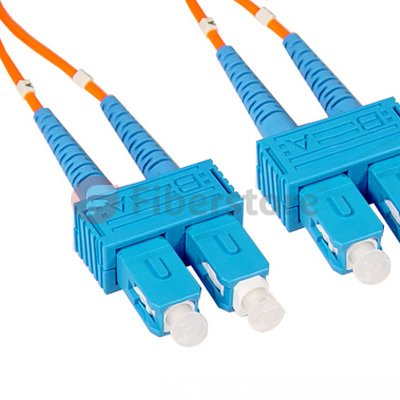 SC-SC Plenum Duplex 62.5/125 sc multimode, with SC to SC termination, this fiber optic patch cable is specificially designed for ethernet, multimedia, or communication applications. The SC connector features a push-pull locking system. The plenum rating provides the fire protection required to run this cable within walls and air plenums without using conduit. The patented injection molding process provides each connection greater durability in resisting pulls, strains and impacts from cabling installs.
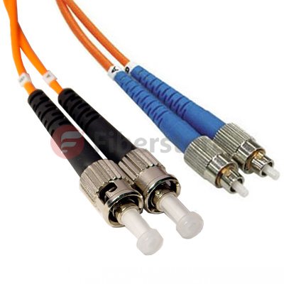 lc lc multimode has a bayonet-style housing and a long spring-loaded ferrule hold the fiber. They are available in both multimode or singlemode versions. Horizontally mounted simplex and duplex adapters are available with metal or plastic housing.
Posted by: mikofy at
04:15 AM
| No Comments
| Add Comment
Post contains 454 words, total size 4 kb.
June 24, 2014

There are some related duplex sc-sc patch cord from our store, the following picture, you can see.

This is an "Yellow" single-mode cable with a 9 μm core and 125 μm cladding diameter. The cable has a color-coded Dual SC connector on each end. Cost-effective solution that provides high bandwidth and transmission rates over longer distances. With SC to SC termination, this high-quality fiber optic patch cable is specifically designed for Gigabit Ethernet applications. The patented injection molding process provides each connection greater durability in resisting pulls, strains and impacts from cabling installs.
The first step in verifying the polarity of the chanels shown in Figure17.28 is to de-enrgize the equipment at both ends of the network,Since lathced duplex patch cords are used,unlug both connectors from both ends of the patch cords at each of the network.Using the continuity tester,verify that connectors on each end of a patch cord are oriented so position A goes to positionB .You can do so byinserting the ferrule of the A position connector into the continuity teseter as shown in Figure17.31.
With the connecetor inserted,energize the continutity tester and check to see if light is exiting the optical fiber in position B at the oppotite the path cord.if light is exiting the optical fiber in position B,the polarity is correct.if ligtht is exting the optical fiber in position A,the polarty is not correct.With the continuity tester still attached and energized ,unlatch both conectors,seap locations,and relatch.Verify light is extiing forem the optical fiber in positon B.Repeat this for the other fiber optic patch cords and correct as necessray.
With both patch cords properly configred,the next step is to verify the polarity the horizontal cabling .To minimize accses to other horizontal cabling,you should work from the equipment outlet to the pach panel.REmove the cover of the equipment outlet and plug both connectors at one end of the path cord into the receptacles on the equipment ontlet.Do not disturb the horionta cabling connections.
Insert the ferrule of the A postion connector at the end of the patch cord into the continuity tester as shown earlier in Figure17.31.With the connector inserted,engrgize the continuity tester as shown earlier in Figure 17.31.With the conector inserted,energize the continuity teser and check to see if light is exiting the horizontal cabling optical fiber in positionB at the pach panel.If light is exiting the optical fiber in postion B,the polarity is not correct.With the continuity tester still attached and energized,unlatch,Light should be exiting from the optical fiber in positionB.Reinstall the equipment outtlet cover.
Posted by: mikofy at
07:54 AM
| No Comments
| Add Comment
Post contains 520 words, total size 4 kb.
31 queries taking 0.0688 seconds, 45 records returned.
Powered by Minx 1.1.6c-pink.

